Redesign of a Cam-Driven Compression System
Context & Objectives
As part of the Advanced Design course at Arts et Métiers (ENSAM) Paris, we were tasked with redesigning the compression system of a champagne bottle capping machine. The original system relied on a pneumatic actuator to displace a linear cam, which was no longer sufficient to meet the increased target throughput of 1800 bottles per hour (versus 800 previously). We designed a fully mechanical cam-driven alternative that delivers the required force and cadence, while ensuring robust and compact integration.
- Target throughput: 1800 bottles/hour
- Compression force: 16,173 N
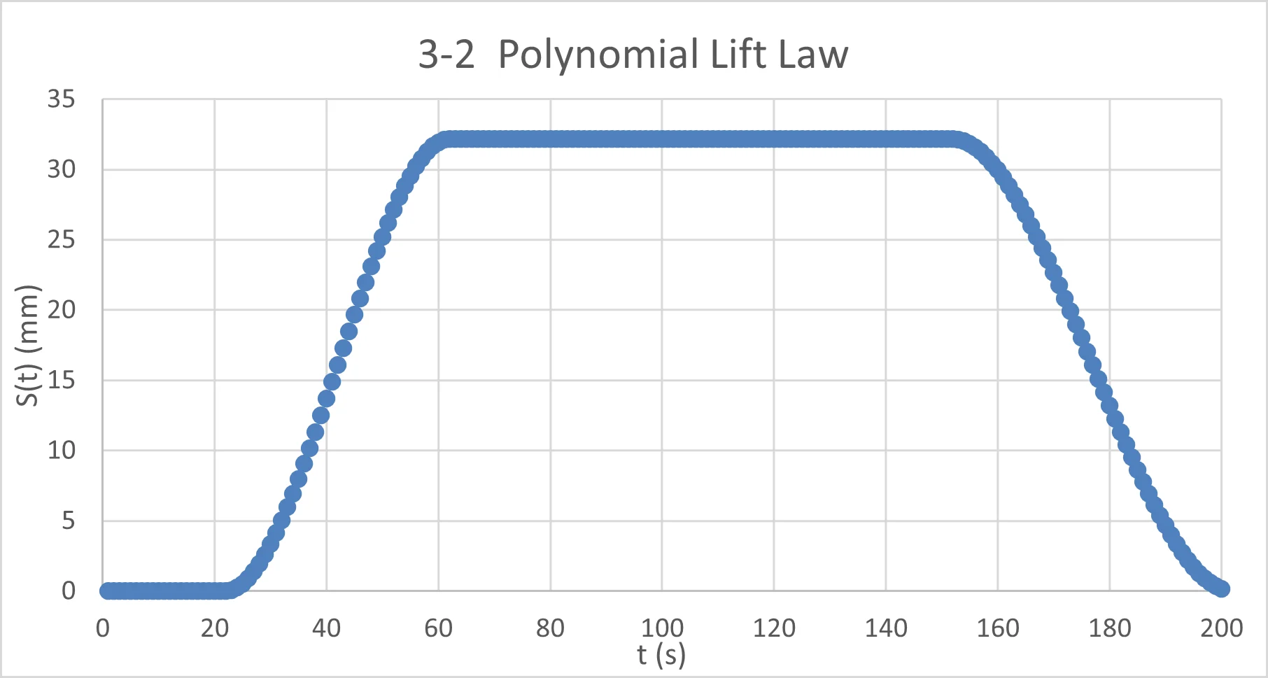
- Cam lift law: 3–2 polynomial
- Material: C18 Steel (Re = 650 MPa)
Design Methodology & Mechanical Validation
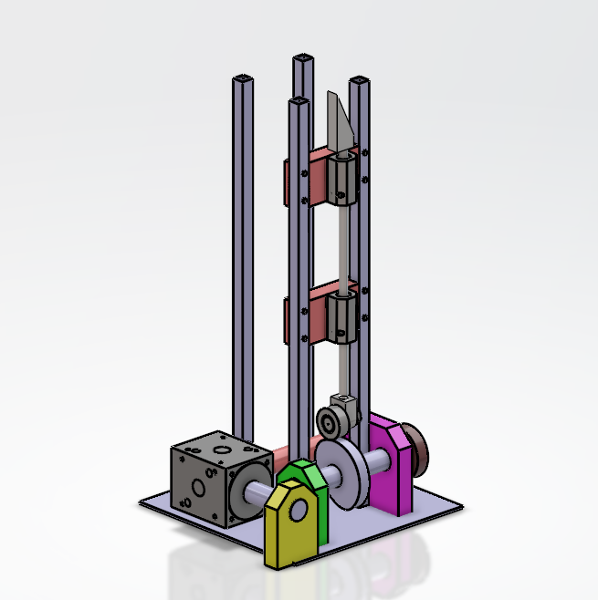
We developed and validated a new compression system based on rotary and linear cams. Key elements of the design included:
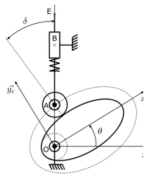
- Choice of a 3–2 polynomial cam lift law for smooth, continuous motion without lift-off
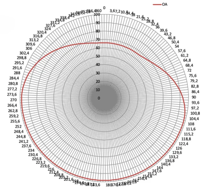
- CAD modeling of theoretical and real cam profiles using Excel and CATIA
- Integration of a KRV-72-PP roller bearing, designed to transmit up to 16,173 N without interference
- Selection of C18 steel (Re = 650 MPa), validated against Hertz contact pressure
- Dimensioning and validation of the sliding guide (glissière) and its constraints
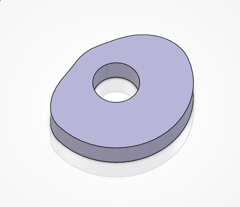
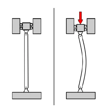
Buckling Simulation in Abaqus
To ensure mechanical stability of the coulisseau ("longe") under compressive loading, we performed a linear buckling analysis in Abaqus. The workflow included:
- Importing 3D geometry from CATIA
- Material: C18 steel (E = 210 GPa, ν = 0.3)
- Applied axial load: 16,173 N
- Mesh: 64,831 tetrahedral elements (C3D10)
- Boundary conditions: fixed base and top guided via sliding contact
The simulation yielded a critical buckling load of 90,300 N, confirming a safety factor of 2.8 with respect to the actual load, consistent with theoretical estimates.
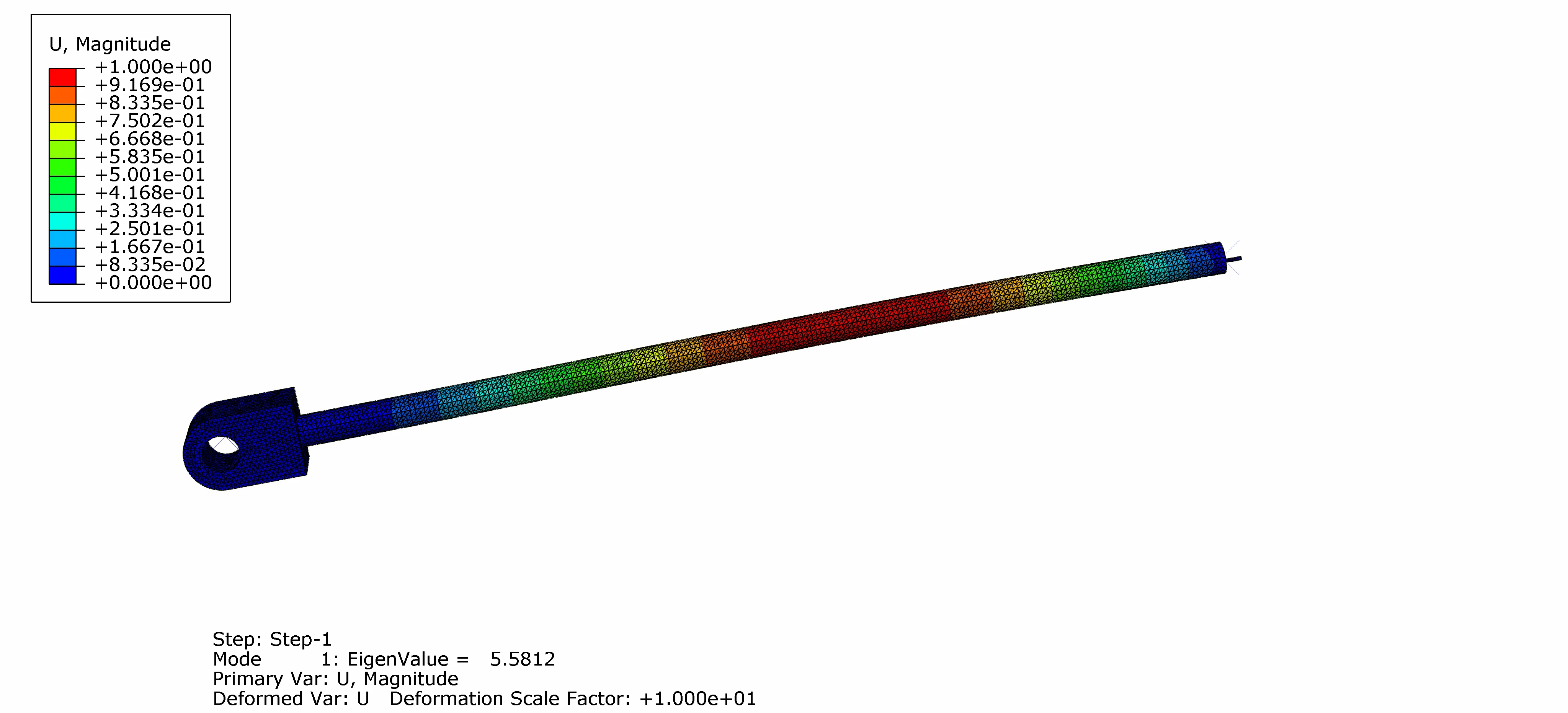
The critical load from simulation (90,300 N) matches the theoretical Euler buckling load (16,173 N × eigenvalue 5.58 = 90,300 N). This cross-validation confirms that the redesigned piston offers a robust mechanical margin, ensuring safe operation under all expected loads.
Results & Key Takeaways
The redesigned cam-driven compression system satisfies all performance and robustness requirements for high-throughput operation. It integrates seamlessly with the existing architecture while eliminating the drawbacks of pneumatic actuation. This project helped me develop and consolidate:
- Skills in cam profile design and lift law optimization
- Mechanical analysis using nonlinear criteria (contact, lift-off, buckling)
- A coherent workflow from CAD to simulation using CATIA and Abaqus
Drafting
The final 2D drawing was the culmination of the design process, translating weeks of kinematic analysis, dimensioning, and mechanical validation into a precise, functional blueprint. Far from being a mere formal requirement, this drawing captured the exact intent of the system — how it moves, how it's assembled, and how it integrates into the existing machine structure.
It reflects every key decision made during the project: the selected cam profile, the travel of the compression shaft, the mechanical interface with the roller, and the spatial constraints imposed by the GBMA architecture. This final deliverable served as the reference for feasibility, integration, and validation of our design.
Acknowledgments
I would like to thank my teammate Romane Soulier for her collaboration and dedication throughout this project as well as Prof. CAESTECKER (ENSAM) for his guidance and constructive feedback during the design.